Display
Understanding the Display
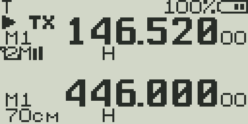
The UV-K5 display packs a lot of information into a small LCD. This page explains every icon, bar, and indicator.
Status Bar (top row)
The very top row of the display shows global radio state.
| Icon / Indicator | Meaning |
|---|---|
| TX | Radio is currently transmitting |
| RX | Radio is currently receiving (audio playing) |
| SCA / SCB | Scan is running on VFO A or VFO B |
| DW | Dual Watch is active |
| VOX | VOX (voice-operated transmit) is enabled |
| KEY / 🔒 | Keypad lock is active — press and hold # to unlock |
| F | F-key modifier is armed — next key press executes F+key shortcut |
| Battery | 5-segment bar on the right side. Blinks when critically low. In some firmware builds shows voltage (e.g., 7.4V) or percentage. |
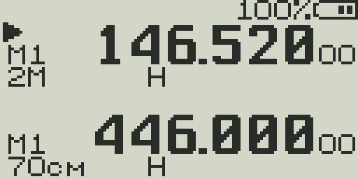
VFO Line 1 — Frequency / Channel
Each VFO has two display lines. Line 1 shows the primary identifier.
| Element | Description |
|---|---|
| ▲ / ▼ marker | Triangle points to the active VFO. Active VFO responds to tuning and PTT. |
| TX / RX icon | Small TX or RX indicator next to the VFO when actively transmitting or receiving on that VFO. |
| Frequency | In VFO mode: frequency in MHz (e.g., 146.520). In channel mode: channel number (000–199) or channel name. |
| MR / VFO indicator | MR shown when in memory channel mode. Absent when in VFO mode. |
| SL1 / SL2 | Scan list membership icons. Shown when the channel/frequency is in Scan List 1 or Scan List 2. |
VFO Line 2 — Settings Summary
Line 2 shows the operating parameters for that VFO in a compact row of icons.
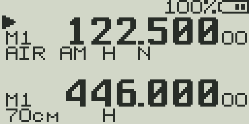
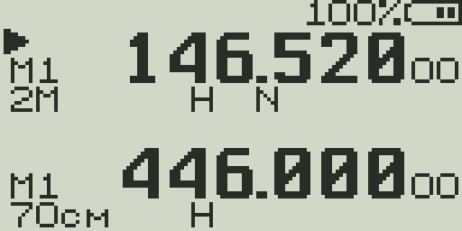
| Icon | Values | Meaning |
|---|---|---|
| Modulation | FM / AM / USB | Demodulation mode. FM for voice/repeaters, AM for aircraft, USB for SSB/HF. |
| Power | L / M / H | TX power: Low (~0.5 W), Mid (~2 W), High (~5 W approx). |
| Offset | + / − / ± | Repeater offset direction: + (positive offset), − (negative offset), ± (split/cross). Blank = simplex. |
| REV | REV | Frequency reverse is active — listening on the repeater's TX (your RX) frequency. |
| Bandwidth | W / N | Wide (25 kHz) or Narrow (12.5 kHz) filter. Narrow reduces adjacent-channel interference. |
| DTMF | DTMF | DTMF encoding is enabled for this channel. |
| SCR | SCR | Scrambler is active on this channel. |
| Signal bars | 1–5 bars | Received signal strength (RSSI) shown as a bar graph. Only visible when squelch is open. |
Band Labels (rfsplatter Firmware)
rfsplatter firmware displays a short band name on the VFO info line alongside the frequency. The label updates automatically as you tune across the radio's receive range, giving you an immediate visual indication of which band you are on.
| Band | Range | Label |
|---|---|---|
| F1 | 18–108 MHz | SW/6M |
| F2 | 108–137 MHz | AIR |
| F3 | 137–174 MHz | 2M |
| F4 | 174–350 MHz | VHF+ |
| F5 | 350–400 MHz | 350 |
| F6 | 400–470 MHz | 70cm |
| F7 | 470–1300 MHz | UHF+ |
Center Line — RSSI / Audio Bar
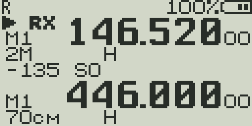
The thin bar between the two VFO displays is the most information-dense part of the screen.
- RSSI bar (receive) — A horizontal bar showing received signal strength. The left side of the bar is accompanied by a dBm reading (e.g.,
−107) and an S-unit (e.g.,S3). Updates continuously regardless of whether squelch is open. - Audio bar (transmit) — During PTT, the RSSI bar switches to a TX audio level bar showing microphone input level.
- DTMF decode — When a DTMF tone is detected on receive, the decoded character is briefly shown in the center area.
- Charge level — When the radio is charging, a charge indicator may appear in the center area.
S-meter scale
| S-unit | Approx. dBm (VHF) | Description |
|---|---|---|
| S0 | < −127 dBm | Noise floor / no signal |
| S1 | −127 dBm | Barely perceptible |
| S3 | −115 dBm | Weak signal |
| S5 | −103 dBm | Fair signal |
| S7 | −91 dBm | Good signal |
| S9 | −73 dBm | Strong signal |
| S9+10 | −63 dBm | Very strong |
| S9+20 | −53 dBm | Extremely strong / local |
Note: The UV-K5 S-meter is calibrated from the RSSI register and is approximate. Values reflect relative signal strength rather than calibrated amateur radio S-units.
Battery Indicator
- 5 segments — Each segment represents approximately 20% charge. All 5 filled = full.
- Blinking — Battery is critically low. Charge soon to avoid unexpected shutoff.
- BatVolt display — If enabled in the menu (BatSave → BatVolt), the battery voltage (e.g., 7.4V) is shown numerically instead of the bar.
- Percentage display — Some firmware builds show battery percentage (e.g., 85%) instead of the bar graph.
- Charging — When connected to USB power, a charging icon or animation replaces or supplements the battery display.
Battery voltage reference
The UV-K5 uses a 7.4V (2S) lithium battery pack. Full charge is ~8.4V; the cutoff is ~6.8V. Use the BatCal menu item to calibrate the voltage reading if it reads inaccurately.
Display Backlight
- Backlight activates on any keypress or PTT press.
- Timeout is set by the BLTime menu item (Off, 5s, 10s, 20s, 1min, 2min, Always On).
- Backlight brightness is set by BLMin/BLMax for off-state dimming and active brightness.
- The backlight also activates when a signal opens squelch (configurable via BLRxTx).