From a phone-mounted mesh radio to hardware for portable and solar installations. Follow the boards, enclosures and companion app from design to testing.
· Hardware
VEIL A5: one board, more possibilities
VEIL A5 is the next step for our mesh hardware. The original VEIL already sends and receives mesh messages and connects to our private iPhone app. A5 builds on that work with a narrower board, a new radio front end, onboard location and more flexible power options.
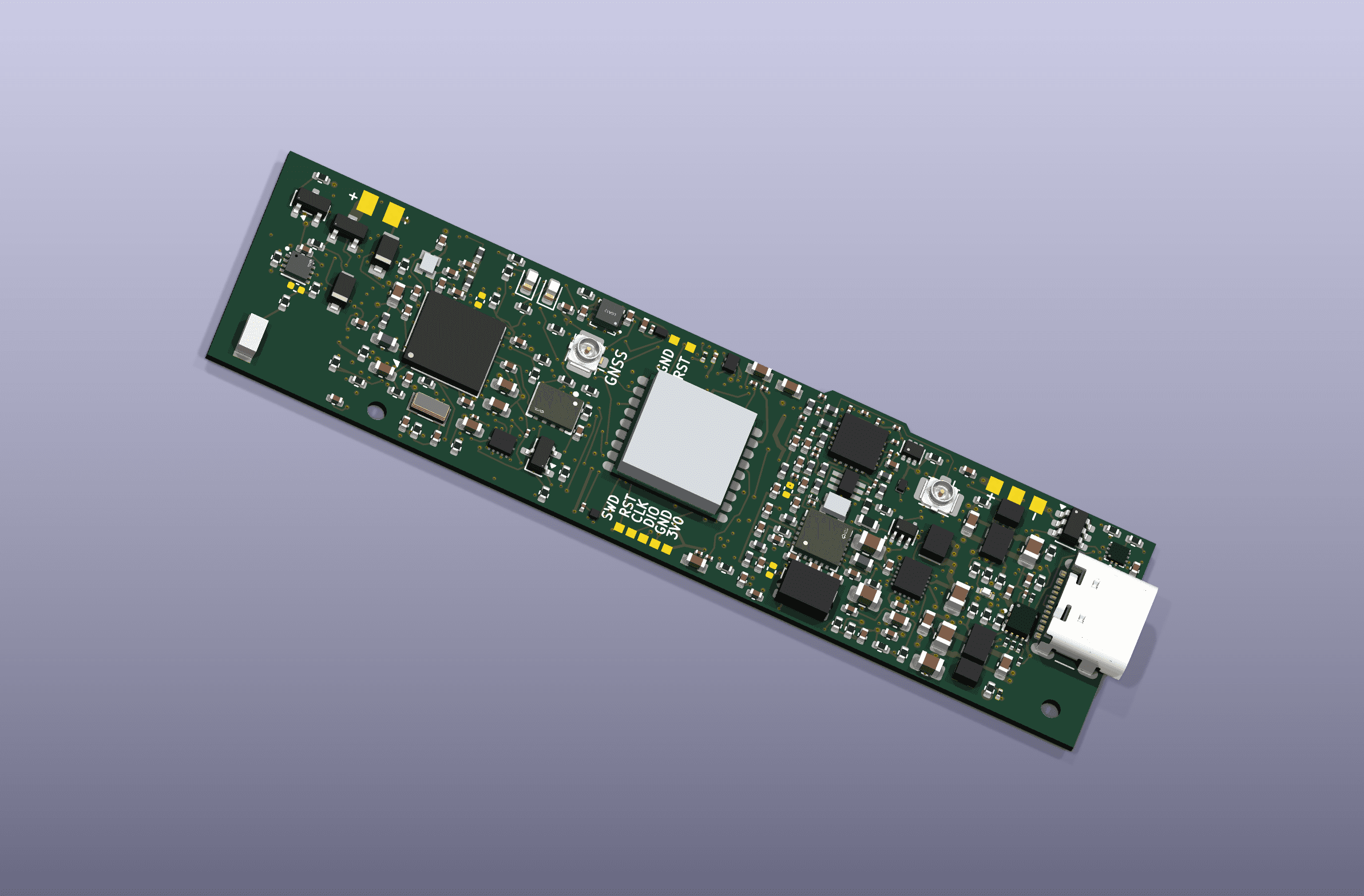
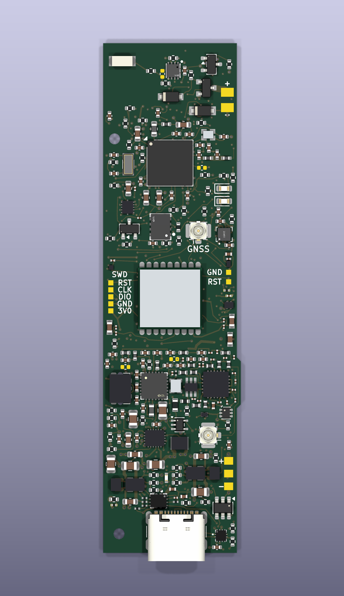
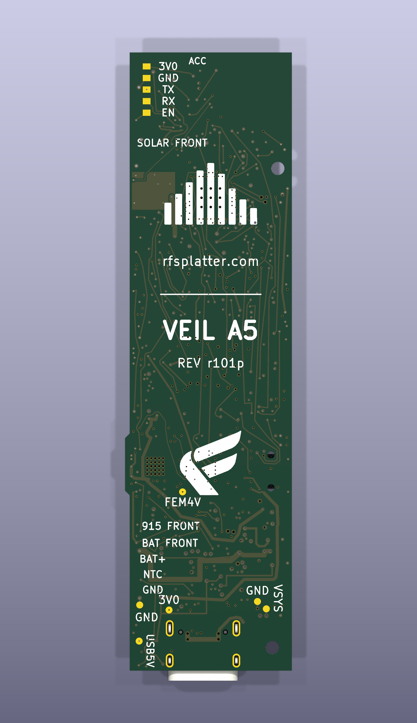
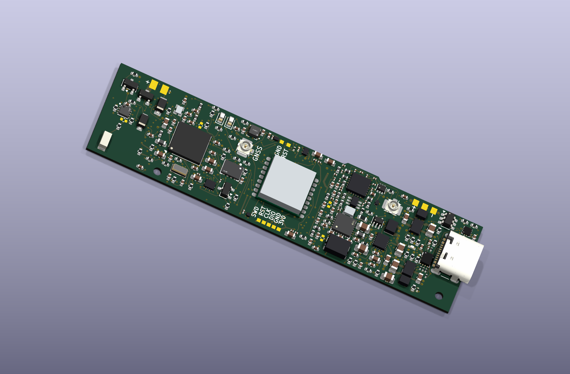
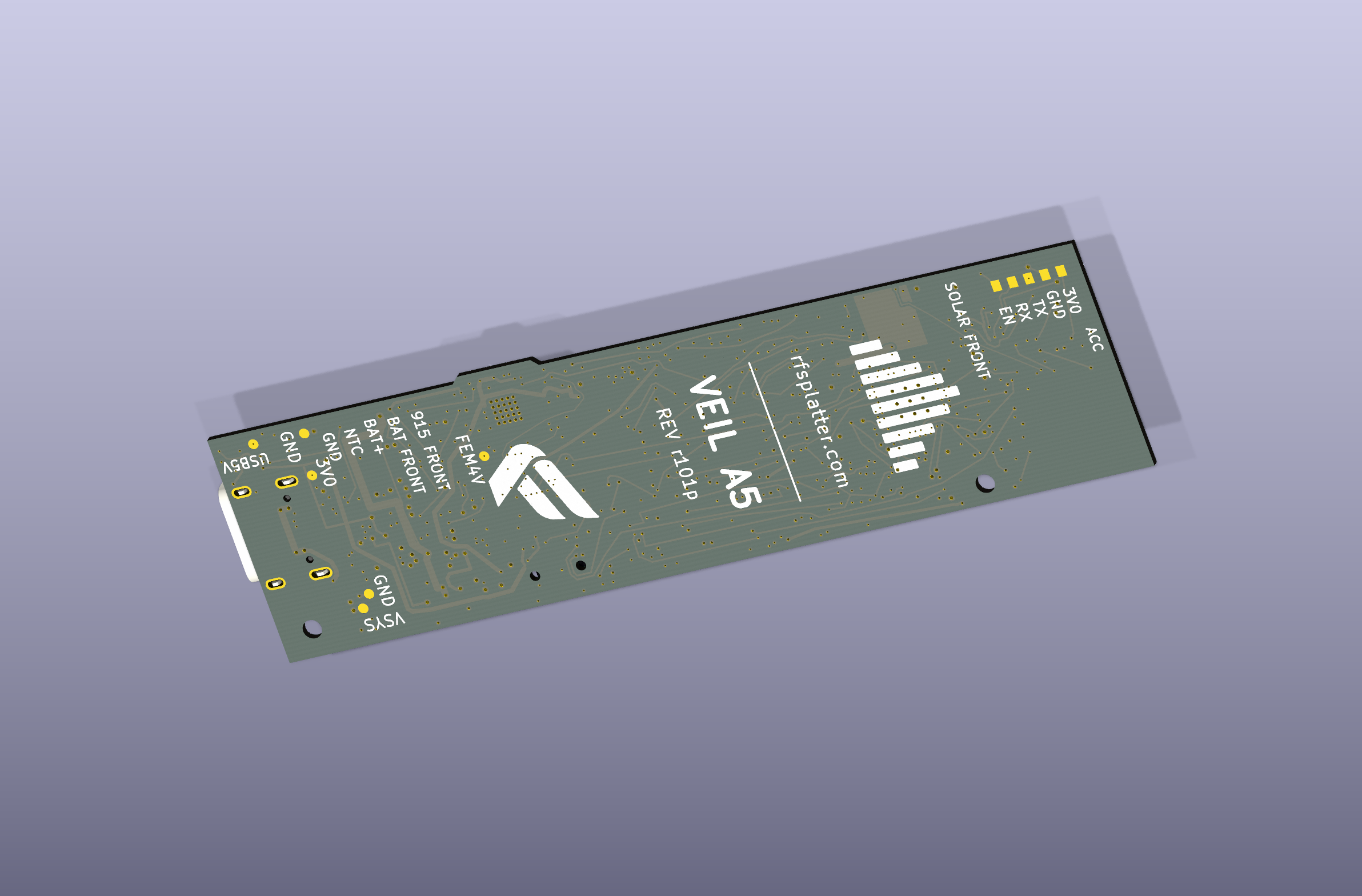
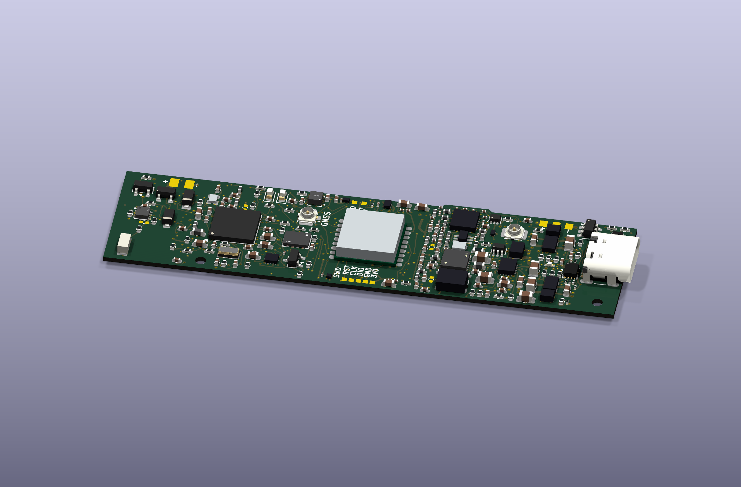
The A5 r101p board design, rendered in KiCad.
What changes with A5
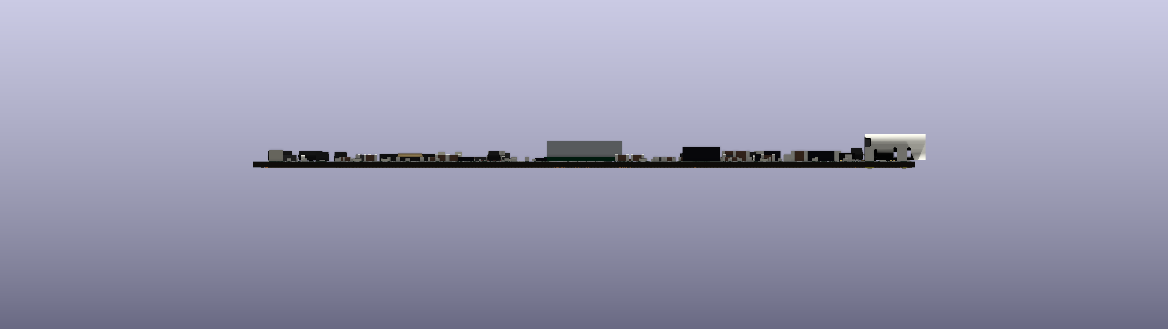
The board is 21.6 × 80 mm, compared with 30 × 75.2 mm on the original. That narrower shape leaves more space beside the electronics for a battery. The eight-layer PCB is 0.8 mm thick before components.
Radio: an SX1262 with an external amplifier and receive front end, targeting up to 1 W transmit power versus roughly 160 mW on the original design.
Location: onboard GNSS and a separate antenna connection for location without relying on the phone.
Power: updated battery charging and regulation, a fuel gauge, temperature monitoring, protected solar input and automatic USB/solar source selection.
Development: motion sensing, 4 MB external flash, labeled test pads, SWD programming access and two locating holes for the enclosure.
These are design capabilities, with RF output, receiver performance, charging behavior and battery life still to be measured on the new boards. MeshCore or Meshtastic support is planned, one firmware at a time; the A5 firmware port is next.
A phone case, a portable node, a solar repeater
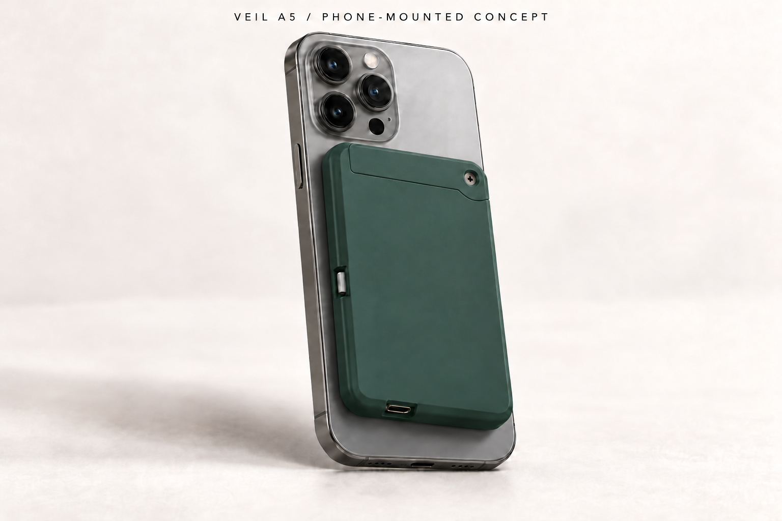
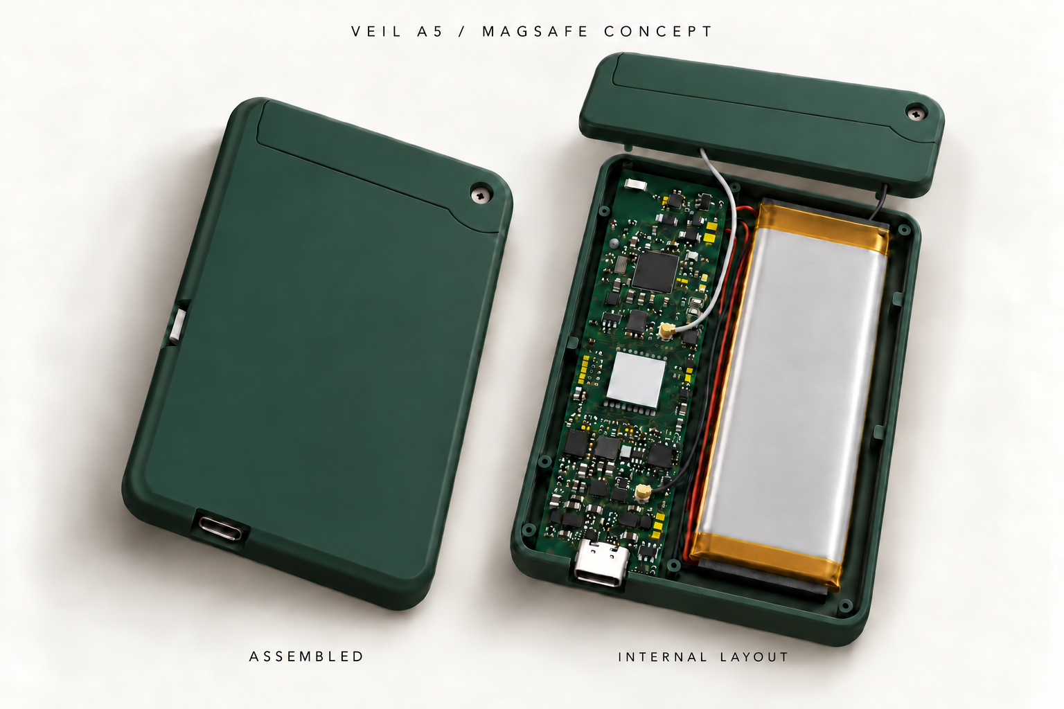
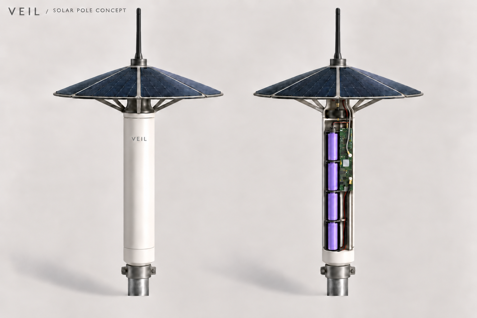
The thin MagSafe case remains the first enclosure. A standalone pocket or clip-on case would use the same board with a different mounting arrangement. For a fixed installation, a cylindrical enclosure would carry a larger battery pack, an external antenna and an angled solar canopy.
MagSafe concept · A smooth lid and a compact phone-mounted form.Proposed internal layout · Narrow board, pouch battery and separate GNSS and 915 MHz antenna leads.Solar repeater concept · End-to-end cells keep the housing narrow.
The enclosure images are AI-assisted design illustrations, not dimensioned CAD assemblies. The solar version still needs a complete winter energy budget, cold-weather charging validation and weather sealing tests. The existing H20 printable case is for the original VEIL board; new A5 case files will follow physical fit checks.
Next on the bench
First comes power-up and programming, then checks of the power rails, charging, GNSS and radio. We’ll measure transmit output, receive performance, current consumption and temperatures before field range and runtime testing. The 1 W target and solar concept need those results before they become performance claims.
Meanwhile, the original hardware remains our app test platform. Messaging and discovery notifications work, and a MeshCore Bluetooth update has been verified. Maps and linked replies are in the private build. The on-device “Catch me up” summary and tiny image transfers remain development work.
A closer look at the board
Six views of r101p. Select any image to open the full-resolution render. Component body details and colors are illustrative.
Printable files for VEIL’s magnetic phone-mounted enclosure are now available. The latest revision, H20, includes a recessed antenna cap that swings out from the case, a side power slider, and a removable antenna backing.
Prototype files — not a final design.
The models have passed CAD and slicer checks. Physical fit, durability and the revised print finish still need testing. These parts are designed for the original VEIL circuit board, not A5.
A recessed antenna and accessible controls
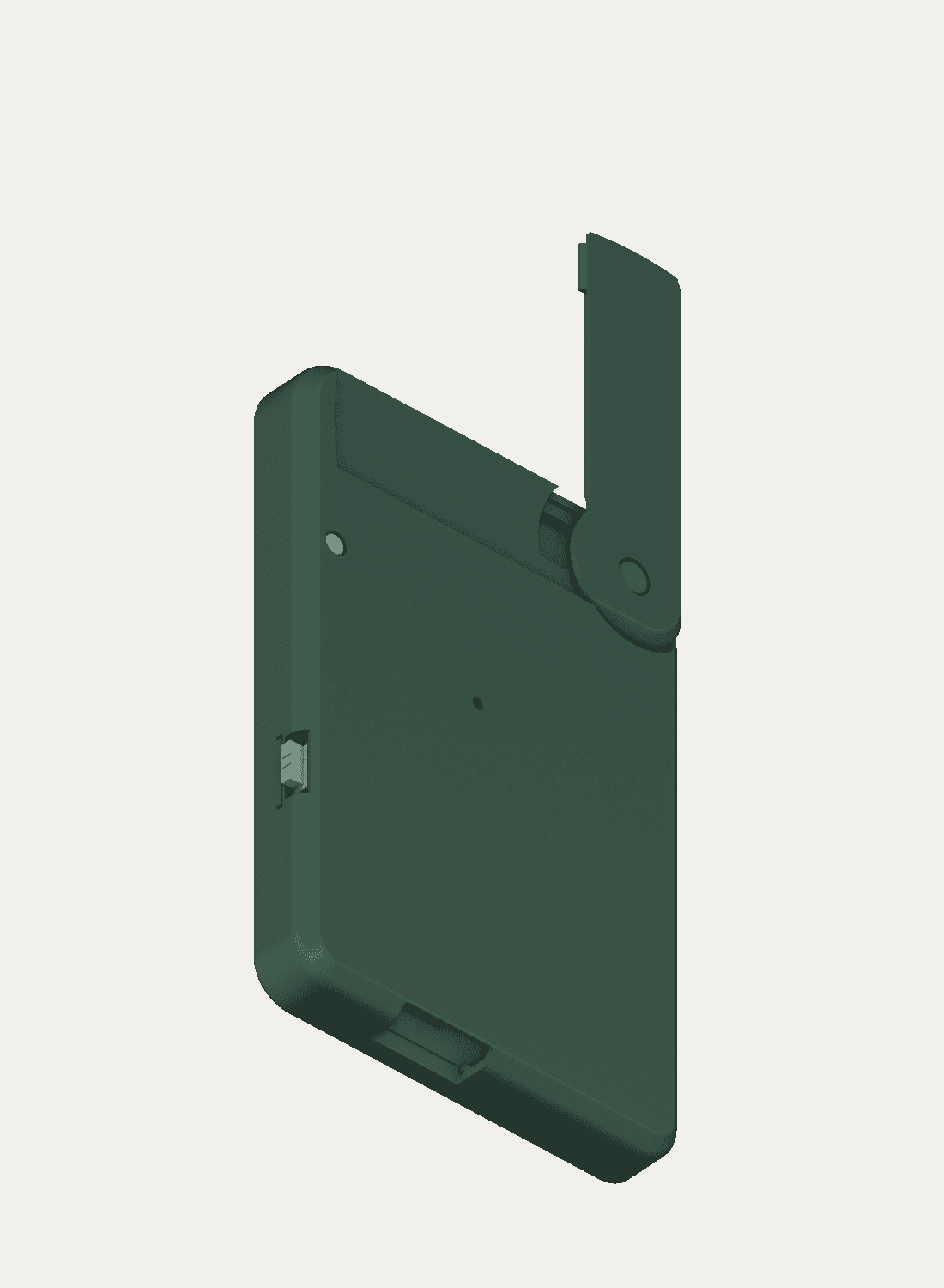
The antenna cap follows the case surface when closed. A small tab retains its free end, and a screw forms the pivot. Opening the cap moves the antenna away from the phone; any effect on radio performance still needs to be measured.
H20 CAD render with the antenna open. Green is used to show the part shapes.
The case measures 64 × 96 mm in the model. A raised side slider provides access to the power switch, while USB-C sits along the bottom edge. The antenna backing slides into the cap for assembly, and the lower case screws are spaced on opposite sides.
What’s in the download
The bundle includes STL files for all six enclosure parts, four Bambu Studio 3MF projects, and a print and assembly guide. The projects are configured for a Bambu P1S with a 0.4 mm nozzle and one spool of Generic PETG. The estimated full-case print time is about two hours.
A small recess sample takes about 29 minutes and lets you check the supported surface before printing the case. The included r2 support profile uses a closer, denser interface to reduce sagging, which may also make supports harder to remove. Its finish has not yet been checked on a physical print.
Use the matching lid and antenna cap together. The guide covers assembly, M2 self-tapping screws and compatibility with earlier VEIL parts. Electronics, magnets, antenna and fasteners are not included.
The first ten VEIL prototype boards have arrived from JLCPCB. An assembled node has connected to an iPhone, discovered MeshCore repeaters, and sent and received messages over the air.
VEIL combines a custom LoRa board, a 600 mAh rechargeable battery, a battery temperature sensor and an antenna in a printed magnetic enclosure. Both Meshtastic and MeshCore have been installed on the hardware. The radio runs one firmware at a time; the two networks do not communicate with each other.
The iPhone app
The private VEIL app supports MeshCore messaging and notifications for incoming messages and discovered repeaters. It distinguishes between discovered radios and saved contacts, and keeps conversations associated with the radio that received them.
Version 0.8.0 also includes maps, offline map downloads, linked replies and saved reply drafts. The reply features have passed automated and simulator checks; testing between physical radios and other apps is still needed.
Replies work differently across the two protocols. Meshtastic has a native message reference. For MeshCore, VEIL includes a username mention and a short reference code in the message text. Other MeshCore apps can read that text, but do not automatically display VEIL’s conversation threads. A reply in a public channel remains public.
Bluetooth firmware updates
A VEIL prototype completed a MeshCore firmware update from the app over Bluetooth while retaining its pairing. The transfer took about four minutes and required a manual reconnection check. Further tests will focus on making the full update and reconnection process reliable.
Switching between MeshCore and Meshtastic over Bluetooth is still in development. The update process has not been validated on other boards.
Image compression research
LoRa’s limited data rate makes ordinary image files impractical to send casually. A desktop experiment is testing whether a shared machine-learning model can encode small, recognizable previews within a 512-byte file budget.
Across 32 test photos excluded from training, the experiment produced files between 503 and 512 bytes. JPEG, WebP, AVIF and PNG were compared at the same size budget. The custom format requires the same model to be installed at both ends and can lose details such as text, facial features and texture.
Those file sizes exclude radio overhead and retries. An image still needs multiple packets, and the current codec has only been tested in local transfer simulations. It is not available in the app or readable by standard mesh apps.
Further development
Upcoming work includes range and battery measurements, charging temperature checks, broader phone-fit testing and reply compatibility. An offline traffic summary, “Catch me up,” is also planned: it would summarize received messages on the phone and link to the originals.
The app remains in private iPhone testing, with Android planned. There is no public app release or hardware preorder yet.
The first prototype boards for VEIL, a magnetic phone-mounted mesh radio, have entered manufacturing. Enclosure development has reached revision H5, which replaces the earlier lid with a flat surface and rounded rim.
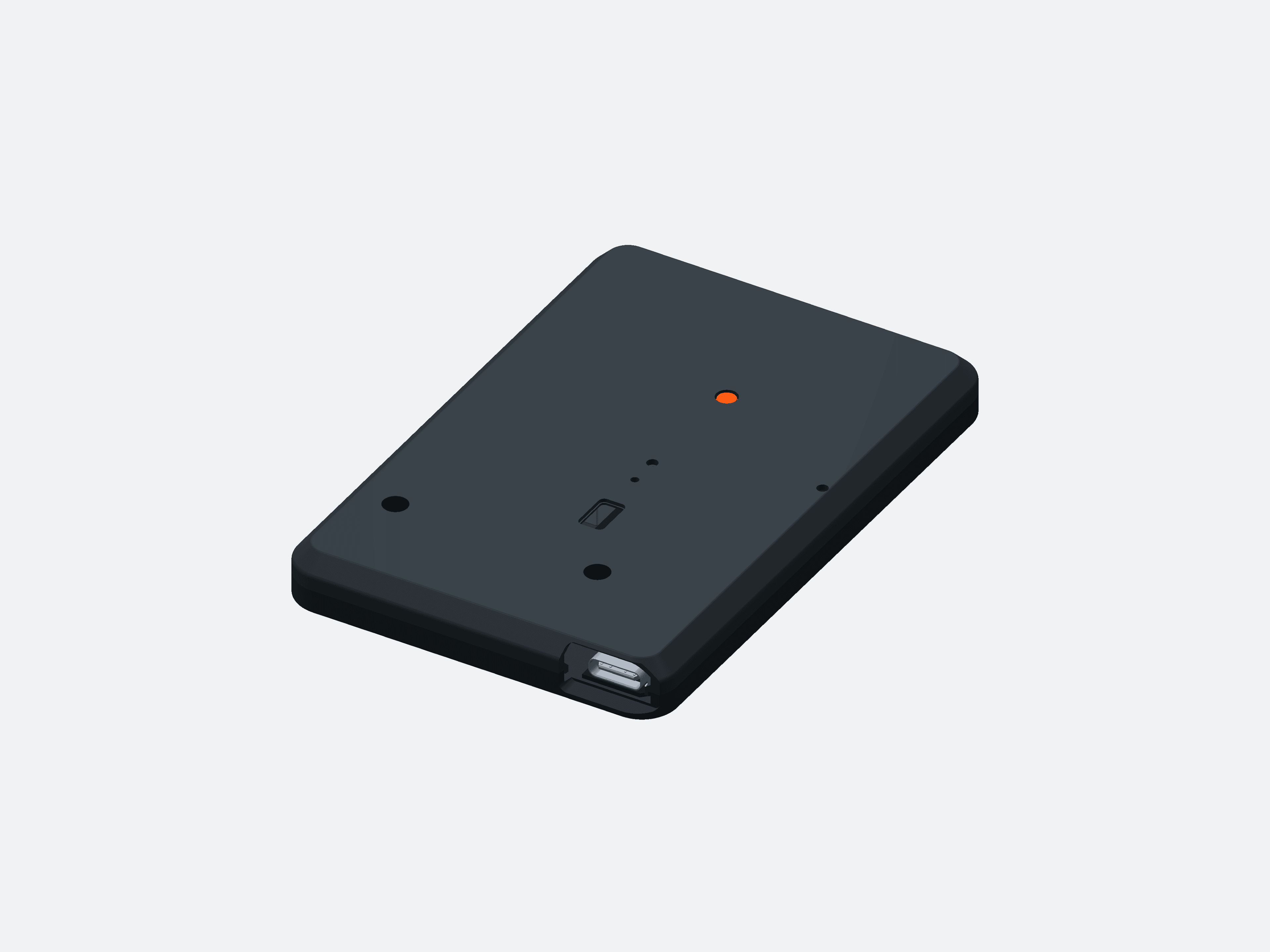
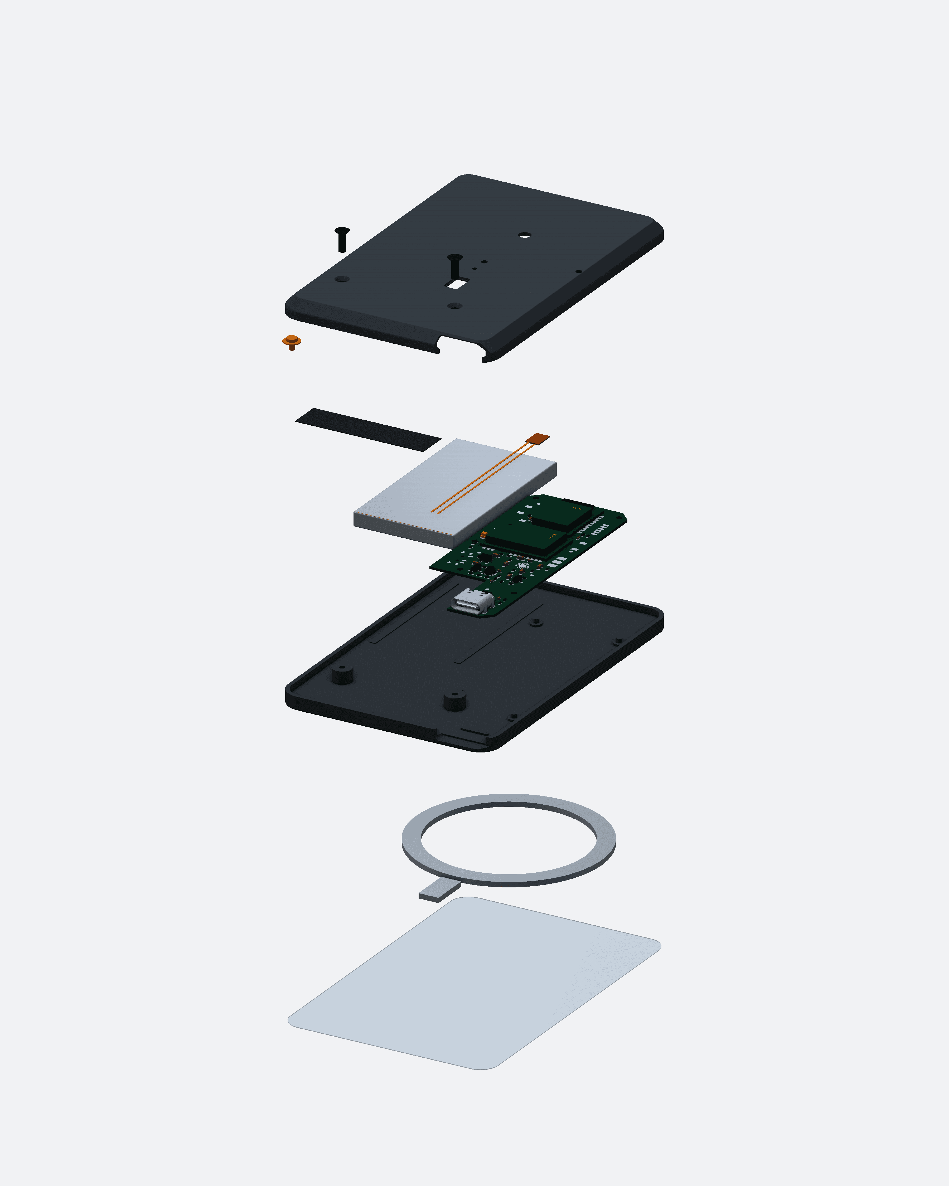
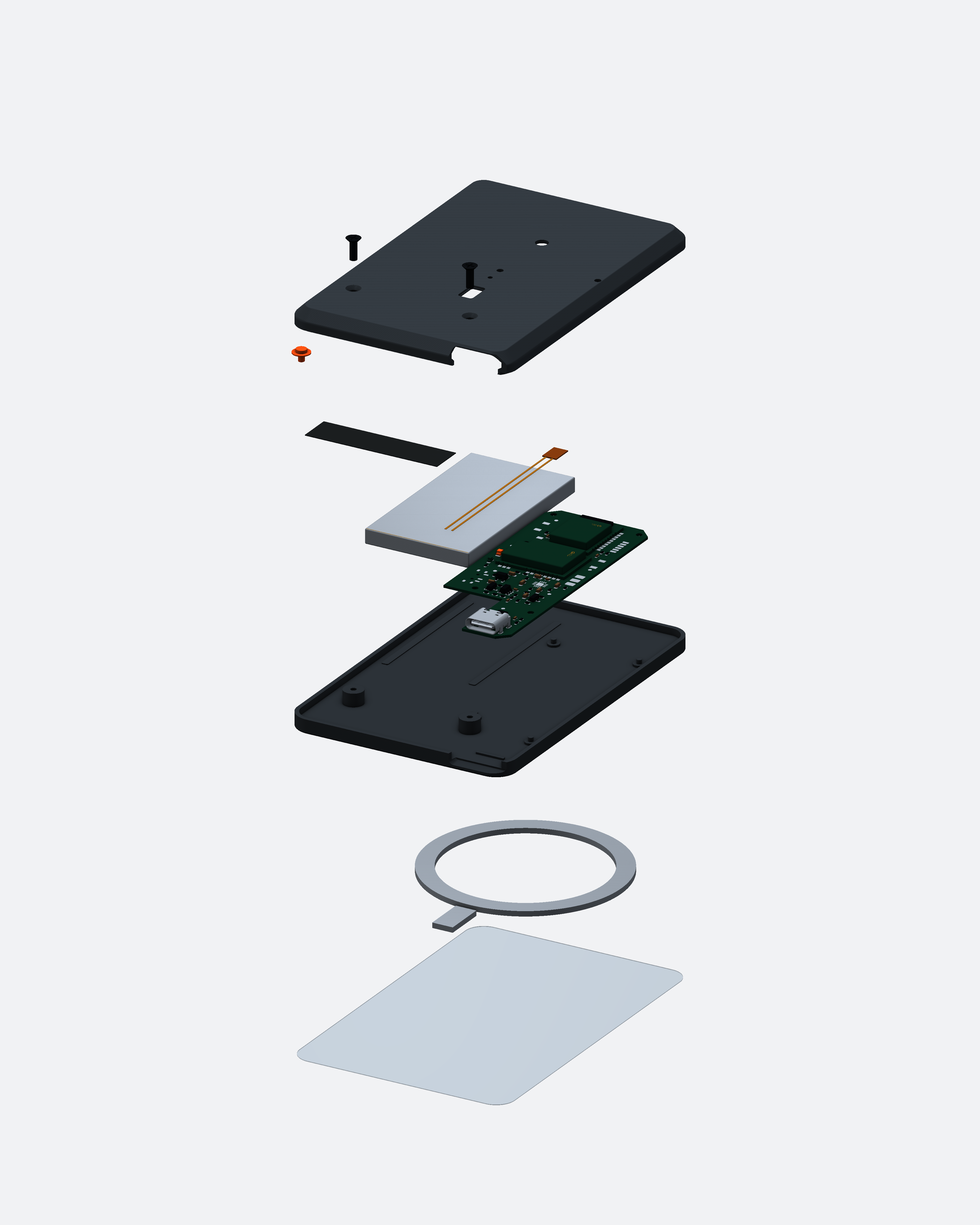
September 8 design: H5 enclosure CAD. Colors are illustrative.
The H5 enclosure
This revision measures 64 × 96 mm, with a modeled thickness of 9.5 mm including the phone-contact film. The flat lid is designed to print face-down without supports. The base, magnet pockets and internal component positions carry over from the preceding design.
USB-C, power-switch, LED and reset access are built into the case. Printed fit and measurements will be checked once the boards are assembled.
H5 components separated for visibility; flexible cables are omitted. View full-size CAD ↗
Assembly and testing
When the boards arrive, testing will begin with power and charging, followed by firmware installation, Bluetooth connection and radio operation. Meshtastic and MeshCore firmware builds compile for the board, but neither has been tested on the physical prototype at this stage.
A separate VEIL ham radio for the 2 m and 70 cm bands is also in design. The enclosure and board shown in this post belong to the mesh project.
VEIL is being designed as a compact LoRa mesh radio that attaches magnetically to a phone. The phone provides the messaging interface over Bluetooth, while the radio carries messages without relying on cell service.
The initial design combines a custom circuit board, a rechargeable battery and an internal antenna in a rounded enclosure. This post documents the early A3 enclosure and A4 board revisions, before physical hardware testing.
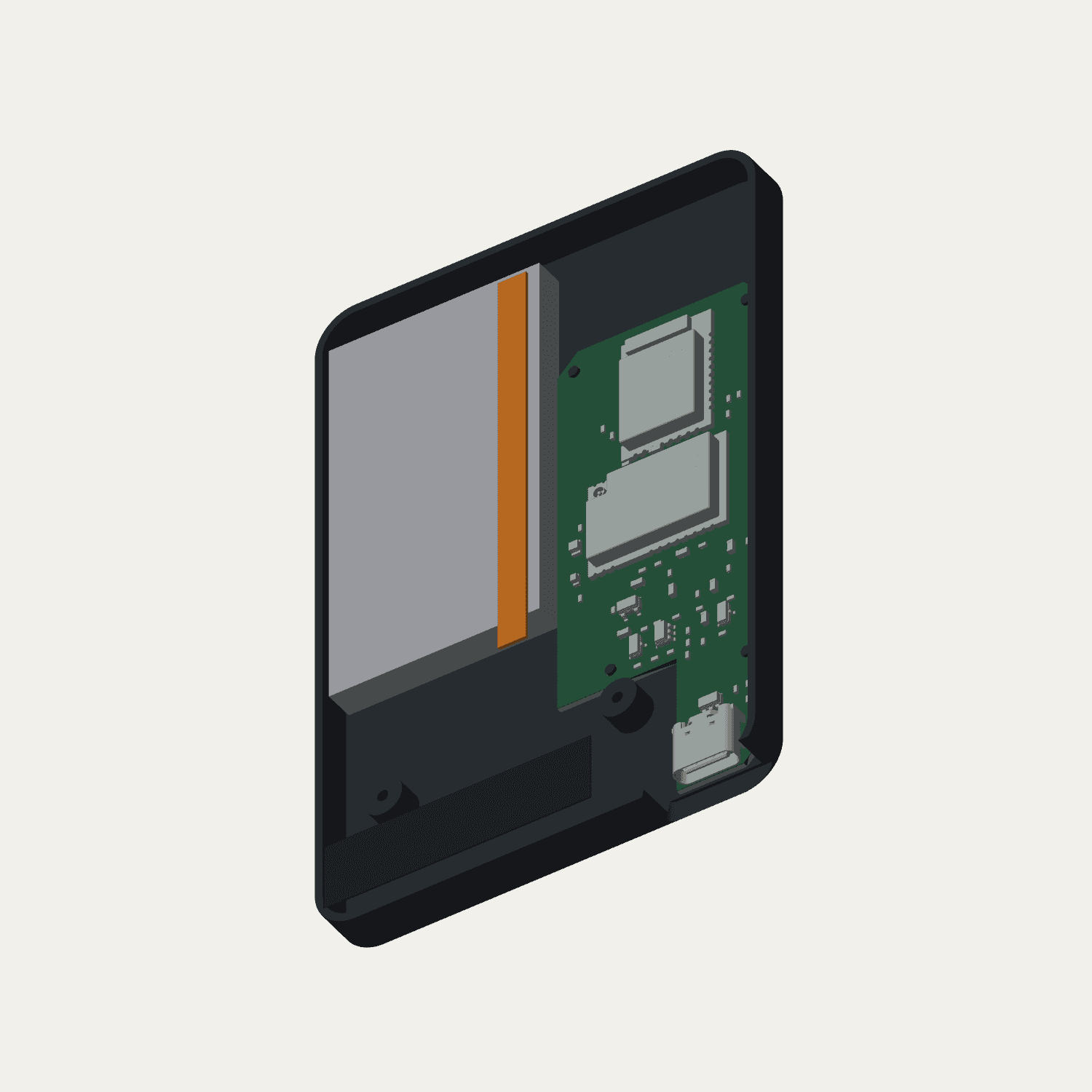
Early A3 enclosure with A4 board and battery fit envelopes.
Fitting the radio around a phone
The case outline is 64 × 96 mm, with an alignment magnet and a USB connection along the bottom edge. Two magnet arrangements give modeled attached thicknesses of 7.4 mm and 8.3 mm. These are design dimensions; printed fit, magnetic retention and camera clearance still need to be tested.
Preparing for the first boards
PCB manufacturing files and firmware builds for Meshtastic and MeshCore are prepared. A blank board will need an SWD programmer for its initial firmware installation.
The first bench tests will check power and charging before moving to firmware, phone connection and radio operation. Range and battery life will be measured on assembled hardware.